 See NOTE below |
Medium resolution, ~126K JPEG High Resolution, ~1.18MB GIF |
 |
Medium resolution, ~178K JPEG High Resolution, ~1.21MB GIF |
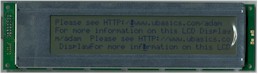
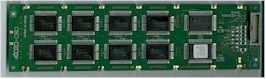
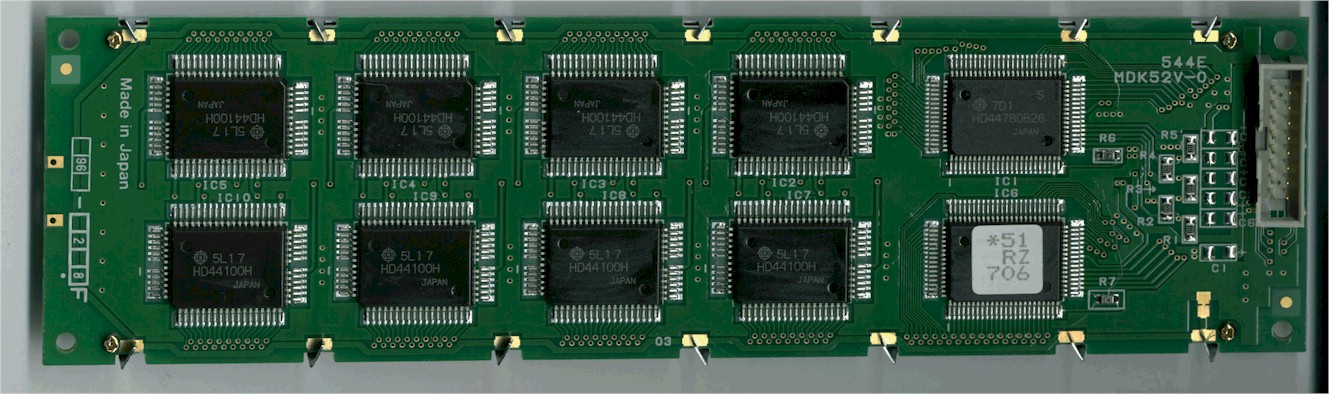
This page discribes the pinout of the Tottori Sanyo LCM54451RZ 4 line by 40 character display currently sold by MPJA as item #12295 OP. Please note that this pinout is NOT an industry standard. It was found by tracing the circuit board of the LCD display and correlating pins on the HD44780 with pins on the connector. I have tested the display, and found that it works in both 4-bit and 8-bit mode as expected. All power, data and control lines are connected to both chips excepting the enable control lines. These are seperate signals for the seperate HD44780s, one which controls the upper two lines of the display, the other controlling the lower two lines of the display. I could not find any data on these displays, and am assuming the specifications are similar to other HD44780 controlled LCD displays.
See NOTE below |
Medium resolution, ~126K JPEG High Resolution, ~1.18MB GIF |
|
Medium resolution, ~178K JPEG High Resolution, ~1.21MB GIF |
| = | Power connections | |
| = | Control lines | |
| = | Data bus | |
| = | Don't Care |
| Pin | Symbol | Level | I/O | Function | Interface | ||
|---|---|---|---|---|---|---|---|
| Idle | Active | 4-bit | 8-bit | ||||
| 1 | DB6 | 0/1 | I/O | Data bus line 6 | |||
| 2 | DB7 | 0/1 | I/O | Data bus line 7 (MSB) | |||
| 3 | DB4 | 0/1 | I/O | Data bus line 4 | |||
| 4 | DB5 | 0/1 | I/O | Data bus line 5 | |||
| 5 | DB3 | 0/1 | I/O | Data bus line 3 | |||
| 6 | DB2 | 0/1 | I/O | Data bus line 2 | |||
| 7 | DB0 | 0/1 | I/O | Data bus line 0 (LSB) | |||
| 8 | DB1 | 0/1 | I/O | Data bus line 1 | |||
| 9 | E1 | 1->0 | I | Enable signal row 0 & 1 | |||
| 10 | E2 | 1->0 | I | Enable signal row 2 & 3 | |||
| 11 | RS | 1 | 0/1 | I | 0 = Instruction input 1 = Data input |
||
| 12 | R/W | 1 | 0/1 | I | 0 = Write to LCD module 1 = Read from LCD module |
||
| 13 | Vee | 0 to -5 VDC | - | LCD Voltage [0 to -5 VDC] (Contrast adjust) I've found -3 VDC to be optimal. |
|||
| 14 | Vcc | 5 VDC +/- 5% | - | Power supply (+5V) | |||
| 15 | Vss | 0 | - | Power supply (GND) | |||
| 16 | Vss | 0 | - | Power supply (GND) | |||
| Symbol | Pin | Level | I/O | Function | Interface | ||
|---|---|---|---|---|---|---|---|
| Idle | Active | 4-bit | 8-bit | ||||
| Vss | 15 | 0 | - | Power supply (GND) | |||
| Vss | 16 | 0 | - | Power supply (GND) | |||
| Vcc | 14 | 5 VDC +/- 5% | - | Power supply (+5V) | |||
| Vee | 13 | 0 to -5 VDC | - | LCD Voltage [0 to -5 VDC] (Contrast adjust) I've found -3 VDC to be optimal. |
|||
| E1 | 9 | 1 | 1->0 | I | Enable signal row 0 & 1 | ||
| E2 | 10 | 1 | 1->0 | I | Enable signal row 2 & 3 | ||
| RS | 11 | 0/1 | I | 0 = Instruction input 1 = Data input |
|||
| R/W | 12 | 0/1 | I | 0 = Write to LCD module 1 = Read from LCD module |
|||
| DB0 | 7 | 0/1 | I/O | Data bus line 0 (LSB) | |||
| DB1 | 8 | 0/1 | I/O | Data bus line 1 | |||
| DB2 | 6 | 0/1 | I/O | Data bus line 2 | |||
| DB3 | 5 | 0/1 | I/O | Data bus line 3 | |||
| DB4 | 3 | 0/1 | I/O | Data bus line 4 | |||
| DB5 | 4 | 0/1 | I/O | Data bus line 5 | |||
| DB6 | 1 | 0/1 | I/O | Data bus line 6 | |||
| DB7 | 2 | 0/1 | I/O | Data bus line 7 (MSB) | |||
NOTE: The scans of the LCD are not perfect, notably: I did not remove the
plastic covering from the display face, which caused the white 'quarter moon' on the right
of the display. My scanner is away from my work area, so I had to connect a portable power
supply, and disconnect other connections before scanning. During this switch, the lower
display shifted (I must've been shaking the display too hard...;-)